
How Poor Connection Detailing Affects Structural BIM Projects?
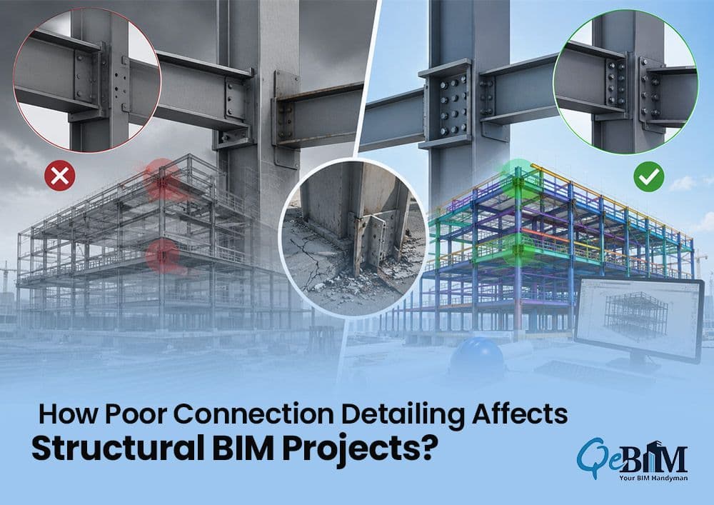
In modern construction projects, structural coordination is no longer limited to beams, columns and slabs alone. The real complexity often lies in the connections — the joints where the structural elements meets and transfers the loads. From steel-to-steel joints to beam-column interfaces, even a minor error in the connection detailing can lead to the fabrication delays, site reworks, increased costs and structural inconsistencies.
This is where BIM plays an important role. Connection detailing in the Structural BIM enables the engineers, fabricators and contractors to visualize, coordinate as well as validate the structural joints before the construction begins. However, despite advanced workflows and software capabilities, mistakes still happen — and often at the most crucial stages.
Why Connection Detailing Matters?
Structural connections are responsible for transferring the forces safely throughout the building framework. Poorly detailed connections can compromise the constructability, installation sequencing and structural performances.
In BIM workflows, connection detailing is not just about geometry. It involves:
Bolt and weld placements
Plate sizing and thickness
Fabrication tolerances
Clash coordination
Load transfer logic
Erection feasibility
Shop drawing accuracy
A coordinated BIM model helps the stakeholders to identify these issues early thus reducing the downstream risks during the fabrication and construction.
Common Areas Where Mistakes Happen
1. Incomplete Design Intent
One of the most common problems occurs when the design drawings lacks the detailed connection information. Structural engineers may define the member sizes and layouts but leaves the fabrication-level connection decisions incomplete.
This creates ambiguity during the modeling and detailing, especially in fast-track projects.
Typical issues includes:
Undefined connection types
Missing weld specifications
Inadequate bolt information
Lack of load path clarification
Without clear intent, detailers are forced to make assumptions that may not align with the fabrication or site conditions.
2. Clash Detection Focused Only on Major Elements
Many teams prioritize the clash detection between major disciplines such as architecture, structure and MEP. However, smaller connection components often get overlooked.
Common overlooked clashes includes:
Bolt interference with ducts or pipes
Connection plates conflicting with the embeds
Weld access restrictions
Insufficient installation clearance
Even when primary structural elements appear coordinated, unresolved connection clashes can create major site-level challenges.
3. Incorrect Modeling Levels of Detail (LOD)
Using the wrong Level of Detail can significantly impact the connection accuracy.
For example:
LOD 200 models may only represent approximate geometry
LOD 300 introduces more accurate placement
LOD 400 includes fabrication-ready connection details
Problems arises when the projects attempt fabrication using the models that lacks sufficient detailing intelligence.
Accurate connection detailing requires:
Precise geometry
Fabrication tolerances
Hardware specifications
Assembly sequencing considerations
4. Poor Coordination Between Engineer and Fabricator
Structural engineers and steel fabricators often work with different priorities. Engineers focus on the structural behavior, while fabricators prioritizes manufacturability and erection efficiency.
Without proper BIM coordination:
Connections may be difficult to fabricate
Welds may become inaccessible
Bolt installation may not be feasible onsite
Steel members may require reworks
Collaborative BIM workflows helps to bridge this gap by enabling all stakeholders to review the constructability before the production begins.
5. Ignoring Site Tolerances and Erection Conditions
A connection that works perfectly in software may fail in the field if real-world tolerances are ignored.
Common site-related issues includes:
Misaligned anchor bolts
Uneven slab levels
Limited crane accessibility
Restricted installation space
Connection detailing should account for practical erection conditions, not just the idealized geometry.
6. Inconsistent Standards Across Teams
Global projects often involves multiple consultants, subcontractors and fabrication teams working across the regions. Different standards and detailing practices can lead to inconsistencies in connection modeling.
Examples include:
Mixed bolt standards
Different weld notation systems
Varying plate thickness conventions
Inconsistent naming structures
Standardized BIM workflows helps to maintain the uniformity across the project lifecycle.
The Role of BIM in Preventing Connection Errors
Advanced BIM workflows significantly reduces the connection-related issues through:
Intelligent 3D Modeling
Detailed models allows the teams to visualize every connection before the fabrication begins.
Automated Clash Detection
BIM tools identify the physical conflicts early thus minimizing the onsite surprises.
Fabrication Integration
Fabricators can directly extract the shop drawings, NC files and material data from the coordinated models.
Improved Communication
Shared BIM environments enables the engineers, contractors and fabricators to work together in real time.
Better Construction Sequencing
Teams can evaluate the erection feasibility and installation logic before the site execution.
Best Practices for Accurate Connection Detailing
To minimize the connection-related errors, project teams should:
Define detailing responsibilities early
Establish BIM execution standards
Use appropriate LOD requirements
Coordinate regularly with the fabricators
Validate constructability through reviews
Perform detailed clash detection for connections
Maintain standardized naming and documentation systems
These practices helps to improve the accuracy, reduce RFIs and streamline the fabrication workflows.
How Technology is Transforming Structural Detailing?
Modern BIM platforms now supports the automated connection libraries, parametric detailing, and fabrication-ready workflows. Tools integrated with Structural BIM Services enable teams to improve precision, coordination, and project efficiency throughout the construction lifecycle.
Similarly, advanced Revit Modeling Services allow engineers and detailers to create intelligent structural models with accurate connection data, enabling smoother collaboration between design and fabrication teams.
Conclusion
Connection detailing is one of the most critical — and error-prone — aspects of structural modeling. While BIM has transformed coordination and visualization, successful outcomes still depend on accurate data, collaborative workflows, and practical construction understanding.
By addressing common detailing mistakes early, project teams can reduce rework, improve fabrication efficiency, and ensure smoother onsite execution. In today’s increasingly complex construction environment, precise connection detailing has become a critical requirement for successful structural execution.